Wednesday, January 22, 2014

How to Remove LCD Screen Lines

 Magic How to Remove LCD Screen Lines.

             http://lcddata.webs.com/


UniMac V4 UniMac Adapter Kit Lines repair
Come and get em' . UniMac V4 is now for sale in the store. This version has elimated a few components which has made a much more solid adapter. This has also of course lead to a reduction in cost and price, so hopefully this will get a lot more of these wonderful iMacs up and runnin
Services

Tuesday, January 21, 2014

Fly Back Transformer Substitute

Fly Back EHT Common Winding Data For Crt TV .


BSC 25 -T 1010A
BSC 25 - N 0816
BSC 25 - N 4014 K
BSC 24- 01N4014 K = 1 2 3 4 5 6 10 / 7 8
~~~~~~~~~~~~~~~~~~~~~~~~~~~~~~~~~~
BSC 24 -01N 4013 K = 1 2 8 / 3 4 5 6
~~~~~~~~~~~~~~~~~~~~~~~~~~~~~~~~~~
BSC 25 -N 4010M
BSC 25 - N 06
BSC 24 -01 N 4010 M = 1 2 7 9 10 / 3 4 5 6
~~~~~~~~~~~~~~~~~~~~~~~~~~~~~~~~~~
AA 26 -00317A
BSC 25 - 00218N = 1 2 / 4 5 6 7 8
~~~~~~~~~~~~~~~~~~~~~~~~~~~~~~~~~~
AA26-00201A ( SAMSUNG TV )
FSV 14A004F
BSC 25 -33662 = 1 3 4 5 6 / 9 10
~~~~~~~~~~~~~~~~~~~~~~~~~~~~~~~~~~
BSC 25 N60
BSC 25 N -N 3260 W
BSC 24 -01N 4006 EV = 2 4 10 / 7 8
~~~~~~~~~~~~~~~~~~~~~~~~~~~~~~~~~~
TS6110126
J0501 - 19949 = 1 2 3 / 4 5 6
~~~~~~~~~~~~~~~~~~~~~~~~~~~~~~~~~~
BSC 23 N 0140 = 1 2 3 /4 5 6 7 9 10
~~~~~~~~~~~~~~~~~~~~~~~~~~~~~~~~~~
BSC 24 - 01N4095M = 1 2 / 3 4 5 6 7 10
~~~~~~~~~~~~~~~~~~~~~~~~~~~~~~~~~~
BSC 24 -01N 4028W
BSC 24 -01N 4095 A = 1 2 3 6 / 5 9 10
~~~~~~~~~~~~~~~~~~~~~~~~~~~~~~~~~~
BSC 24- 01N 4013 E = 1 2 8 / 3 4 5 6
~~~~~~~~~~~~~~~~~~~~~~~~~~~~~~~~~~
BSC 25 -N 1649
6174V - 6006N          = 1 2, 3 4 5 6 8 10
~~~~~~~~~~~~~~~~~~~~~~~~~~~~~~~~~~
EF 22510- 28M15
JF 0501-19526            = 1 2 9 , 3 4 6 7 8
~~~~~~~~~~~~~~~~~~~~~~~~~~~~~~~~~~
BSC 25 -0217G
AA26 - 00305A           = 1 2 , 4 5 6 7 8
~~~~~~~~~~~~~~~~~~~~~~~~~~~~~~~~~~
BSC 25 - N 41
BSC25 - N3141W        = 1 2 4 , 3 5 6 8 10
~~~~~~~~~~~~~~~~~~~~~~~~~~~~~~~~~~
BSC 25 - 01N 4095K   = 1 2 10, 3 4 5 6 7     
1. COL 2. +B 3.VERTICAL 4- VERTICAL 5- GND 6- HEATER 7- ABL 8-   9-  10 - 180V
 ~~~~~~~~~~~~~~~~~~~~~~~~~~~~~~~~~~
BSC 25- N0304  = 1 2, 3 4 5 6 7 8 10
1- COL 2- +B 3- -14V 4- +14V 5-200V 6-GND 7-   8- 28V 9- ABL 10- HEATER 
~~~~~~~~~~~~~~~~~~~~~~

For more details please contact us

How to Read a Schematic

CCFL and LED Store
Schematics are our map to designing, building, and troubleshooting circuits. Understanding how to read and follow schematics is an important skill for any electronics engineer.
This tutorial should turn you into a fully literate schematic reader! We’ll go over all of the fundamental schematic symbols:
Schematic component overview
Then we’ll talk about how those symbols are connected on schematics to create a model of a circuit. We’ll also go over a few tips and tricks to watch out for.

Suggested Reading

Schematic comprehension is a pretty basic electronics skill, but there are a few things you should know before you read this tutorial. Check out these tutorials, if they sound like gaps in your growing brain:


Schematic Symbols (Part 1)

Are you ready for a barrage of circuit components? Here are some of the standardized, basic schematic symbols for various components.

Resistors

The most fundamental of circuit components and symbols! Resistors on a schematic are usually represented by a few zig-zag lines, with two terminals extending outward. Schematics using international symbols may instead use a featureless rectangle, instead of the squiggles.
Resistor schematic symbols

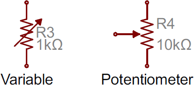
Potentiometers and Variable Resistors

Variable resistors and potentiometers each augment the standard resistor symbol with an arrow. The variable resistor remains a two-terminal device, so the arrow is just laid diagonally across the middle. A potentiometer is a three-terminal device, so the arrow becomes the third terminal (the wiper).
Variable resistor symbols

Capacitors

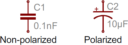
There are two commonly used capacitor symbols. One symbol represents a polarized (usually electrolytic or tantalum) capacitor, and the other is for non-polarized caps. In each case there are two terminals, running perpendicularly into plates.
Capacitors symbols
The symbol with one curved plate indicates that the capacitor is polarized. The curved plate represents the cathode of the capacitor, which should be at a lower voltage than the positive, anode pin. A plus sign might also be added to the positive pin of the polarized capacitor symbol.

Inductors

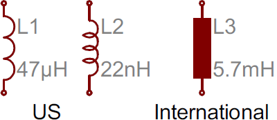
Inductors are usually represented by either a series of curved bumps, or loopy coils. International symbols may just define an inductor as a filled-in rectangle.
Inductor symbols

Switches

Switches exist in many different forms. The most basic switch, a single-pole/single-throw (SPST), is two terminals with a half-connected line representing the actuator (the part that connects the terminals together).
Switch symbol
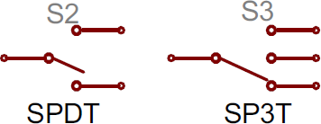
Switches with more than one throw, like the SPDT and SP3T below, add more landing spots for the the actuator.
SPDT and SP3T symbols
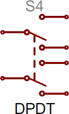
Switches with multiple poles, usually have multiple, alike switches with a dotted line intersecting the middle actuator.
DPDT symbol

Power Sources

Just as there are many options out there for powering your project, there are a wide variety of power source circuit symbols to help specify the power source.

DC or AC Voltage Sources

Most of the time when working with electronics, you’ll be using constant voltage sources. We can use either of these two symbols to define whether the source is supplying direct current (DC) or alternating current (AC):
Voltage source symbols

Batteries

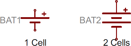
Batteries, whether they’re those cylindrical, alkaline AA’s or rechargeable lithium-polymers, usually look like a pair of disproportionate, parallel lines:
Battery symbols
More pairs of lines usually indicates more series cells in the battery. Also, the longer line is usually used to represent the positive terminal, while the shorter line connects to the negative terminal.

Voltage Nodes

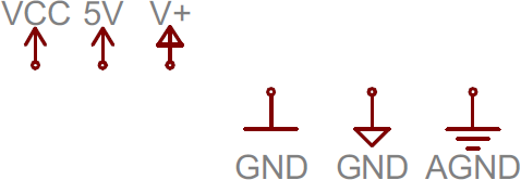
Sometimes – on really busy schematics especially – you can assign special symbols to node voltages. You can connect devices to these one-terminal symbols, and it’ll be tied directly to 5V, 3.3V, VCC, or GND (ground). Positive voltage nodes are usually indicated by an arrow pointing up, while ground nodes usually involve one to three flat lines (or sometimes a down-pointing arrow or triangle).
Voltage node symbols

Schematic Symbols (Part 2)

Diodes

Basic diodes are usually represented with a triangle pressed up against a line. Diodes are also polarized, so each of the two terminals require distinguishing identifiers. The positive, anode is the terminal running into the flat edge of the triangle. The negative, cathode extends out of the line in the symbol (think of it as a - sign).
Diode symbol
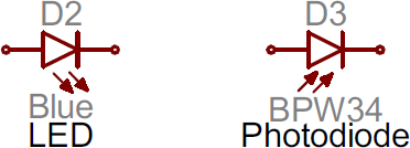
There are a all sorts of different types of diodes, each of which has a special riff on the standard diode symbol. Light-emitting diodes (LEDs) augment the diode symbol with a couple lines pointing away. Photodiodes, which generate energy from light (basically, tiny solar cells), flip the arrows around and point them toward the diode.
LED and Photodiode symbols
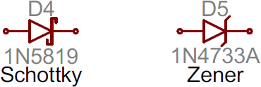
Other special types of diodes, like Schottky’s or zeners, have their own symbols, with slight variations on the bar part of the symbol.
Schottky and zener diode symbols

Transistors

Transistors, whether they’re BJTs or MOSFETs, can exist in two configurations: positively doped, or negatively doped. So for each of these types of transistor, there are at least two ways to draw it.

Bipolar Junction Transistors (BJTs)

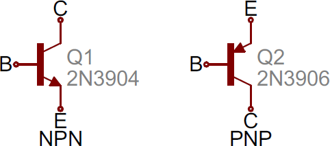
BJTs are three-terminal devices; they have a collector (C), emitter (E), and a base (B). There are two types of BJTs – NPNs and PNPs – and each has it’s own unique symbol.
NPN and PNP BJT symbols
The collector (C) and emitter (E) pins are both in-line with each other, but the emitter should always have an arrow on it. If the arrow is pointing inward, it’s a PNP, and, if the arrow is pointing outward, it’s an NPN. A mnemonic for remembering which is which is “NPN: not pointing in.”

Metal Oxide Field-Effect Transistors (MOSFETs)

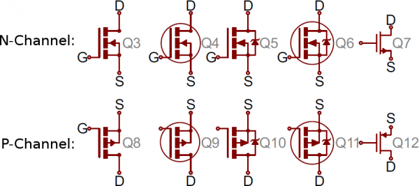
Like BJTs, MOSFETs have three terminals, but this time they’re named source (S), drain (D), and gate (G). And again, there are two different versions of the symbol, depending on whether you’ve got an n-channel or p-channel MOSFET. There are a number of commonly used symbols for each of the MOSFET types:
Variety of MOSFET symbols
The arrow in the middle of the symbol (called the bulk) defines whether the MOSFET is n-channel or p-channel. If the arrow is pointing in means it’s a n-channel MOSFET, and if it’s pointing out it’s a p-channel. Remember: “n is in” (kind of the opposite of the NPN mnemonic).

Digital Logic Gates

Our standard logic functions – AND, OR, NOT, and XOR – all have unique schematic symbols:
Standard logic functions
Adding a bubble to the output negates the function, creating NANDs, NORs, and XNORs:
Negated logic gates
They may have more than two inputs, but the shapes should remain the same (well, maybe a bit bigger), and there should still only be one output.

Integrated Circuits

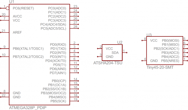
Integrated circuits accomplish such unique tasks, and are so numerous, that they don’t really get a unique circuit symbol. Usually, an integrated circuit is represented by a rectangle, with pins extending out of the sides. Each pin should be labeled with both a number, and a function.
ATmega328, ATSHA204, and ATtiny45 IC symbols
Schematic symbols for an ATmega328 microcontroller (commonly found on Arduinos), an ATSHA204 encryption IC, and an ATtiny45 MCU. As you can see, these components greatly vary in size and pin-counts.
Because ICs have such a generic circuit symbol, the names, values and labels become very important. Each IC should have a value precisely identifying the name of the chip.

Unique ICs: Op Amps, Voltage Regulators

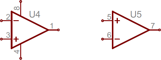
Some of the more common integrated circuits do get a unique circuit symbol. You’ll usually see operation amplifiers laid out like below, with 5 total terminals: a non-inverting input (+), inverting input (-), output, and two power inputs.
Op amp symbols
Often, there will be two op amps built into one IC package requiring only one pin for power and one for ground, which is why the one on the right only has three pins.
Simple voltage regulators are usually three-terminal components with input, output and ground (or adjust) pins. These usually take the shape of a rectangle with pins on the left (input), right (output) and bottom (ground/adjust).
Voltage regulator symbols

Miscellany

Crystals and Resonators

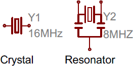
Crystals or resonators are usually a critical part of microcontroller circuits. They help provide a clock signal. Crystal symbols usually have two terminals, while resonators, which add two capacitors to the crystal, usually have three terminals.
Crystal and resonator symbols

Headers and Connectors

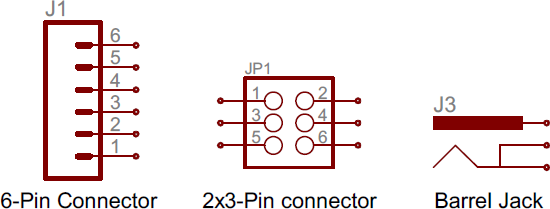
Whether it’s for providing power, or sending out information, connectors are a requirement on most circuits. These symbols vary depending on what the connector looks like, here’s a sampling:
Connector symbols

Motors, Transformers, Speakers, and Relays

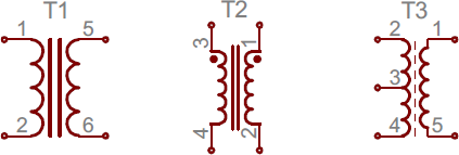
We’ll lump these together, since they (mostly) all make use of coils in some way. Transformers (not the more-than-meets-the-eye kind) usually involve two coils, butted up against each other, with a couple lines separating them:
Transformer symbols
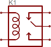
Relays usually pair a coil with a switch:
Relay symbol
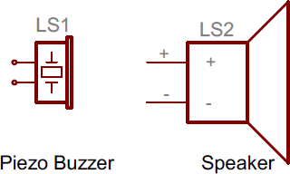
Speakers and buzzers usually take a form similar to their real-life counterparts:
Speaker
And motors generally involve an encircled “M”, sometimes with a bit more embellishment around the terminals:
Motor

Fuses and PTCs

Fuses and PTCs – devices which are generally used to limit large inrushes of current – each have their own unique symbol:
Fuse and PTC symbol
The PTC symbol is actually the generic symbol for a thermistor, a temperature-dependent resistor (notice the international resistor symbol in there?).

No doubt, there are many circuit symbols left off this list, but those above should have you 90% literate in schematic reading. In general, symbols should share a fair amount in common with the real-life components they model. In addition to the symbol, each component on a schematic should have a unique name and value, which further helps to identify it.


NIKAI UHD5501SLEDT Firmware Software Available

NIKAI UHD5501SLEDT Firmware Software Available Follow my page for regular software update NIKAI UHD5501SLEDT Firmware Software Available Mai...