Tuesday, December 31, 2013

Repairing LG 17LX1R LCD Television Power board

Here is a decent looking LCD TV/monitor that would no longer turn on. I expected a few capacitors etc. that needed to be replaced. In this case, it was a single diode at the cost of 29cents and a bit of over 1 hour of labor. It also shows the importance of a good visual inspection. A new power board for this TV would have cost somewhere around 100$

Step 1 — Power board 

  • Here is the LG 17LX1R that will no longer turn on.
  • Remove the cover from the stand by
    • simply pressing down on the two tabs. The cover will come off easily
  • Remove the four screws that hold the stand assembly to the chassis.
Image #1

Step 2 

  • Here again are the four screws to be removed from the stand.
  • Remove the eight Phillips screws that hold the back to the chassis. Once the screws are removed, the back will simply snap off. No excessive force or tools are needed.
  • This is the view with the back off. Time to remove the metal shield. It is fastened with six Phillips screws.
Image #3

Step 3 

  • Remove the two on the left
  • Remove the two on the right.
  • Remove the two on top.
    • Once the six screws are removed the shield can be lifted away easy.
Image #1

Step 4 

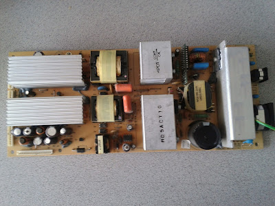
  • After the shield is removed, the power board as well as the main board are immediately visible.
    • Power Board
    • Main Board
    • Fuse
    • Check all capacitors for blown tops and/or leakage.
  • Here is the importance of a good visual inspection. Brown discoloration around Diode D102 is good evidence of a short circuit, possible blown component.
  • Disconnect all connectors from the power board
    • Remove the four screws that mount the power board to the chassis.

Image #1

Image #2


Step 5 

  • Chassis with the power board removed
  • Discoloration of the back side of the power board points again to a bad diode.
  • Unsolder the diode from the power board
    • Replacement diode

Image #3


Image #3


Image #2

Step 6 

  • Here is the unsoldered diode. description on the diode reads LT526 IN4007. Arranged to purchase at $0.29 per diode.
  • Solder the new diode onto the power board. Use a pair of tweezers or hemostat to hold the diode in place while soldering.
  • Diode replaced, clean the board with isopropyl alcohol to get rid of any debris or old flux.
Image #2

Image #1

Thursday, December 26, 2013

AEP016-37 Testing


Olevia 237-T11 power AEP016-37 testing and repair


Download Full Topic

This is a quick pictorial guide on how to test the power supply AEP016-37 found in Olevia 237-T11 and the rest Olevia models that use the same power supply board.

The AEP016-37 power supply is not labeled , but is known to fail and if your Olevia 237-T11 (or other that use it) does not want to start up it may or may not be because of the power supply in it.

One nice way to avoid spending time and money is to just test the power supply out of the box and see if it produces the necessary voltages.

All you need is a simple voltmeter and some patience.

Of course along the way you will also be on the lookout for swollen / bulged capacitors.

Here is how AEP016-37 looks:

http://www.googleadservices.com/pagead/aclk?sa=L&ai=Cut0F48nfUsaoMMnakwWAgIG4CLTVrZED1PL4xFe8z5vbwAEQASChpOMNULGo9af______wFgywSgAYiR-fMDyAEBqAMByAPDBKoEnQFP0BUwmjyGd0DDEMbWBQh32VhKMlfgvpShcTJnKGDBJL1LuLIcLSYTCt5sMvc_5nV5DBdwtT4OZLTw27LFT3kbwTe9AYpL7DlLV1NAtjgDEaIH53BAKhcYhIR0cQs94BDi8CwCoia9VMj-cI3LsWCI-UDtqLfgcdZ6DJN3tuVSQQLvumZZDQJqnVCDPDPpM2vvcnSKDVyLYxWENoCuiAYBgAfg7oYM&num=1&cid=5GjpnRv39afdml9opcaiS-TU&sig=AOD64_3U1s3tCktsPNC8ZwCsfhZ_zT1TuQ&client=ca-pub-1990720073119592&adurl=http://www.alldatasheet.com&nm=4&mb=2&bg=!A0TCBE6NFWeJFgIAAAEJUgAAAEUqAOGbv2hWMOSktAl9olRqsb9vLXJuuxaMPgP5AixWRYRi74boQ0itAXlkYhA66MNyrmY4Oi6nS-yEBoPcbJ42lYv6C4-7W1Ln2PdzI8_ozt2yMzqZerQBLFRd6HToowshyLmTWk6jMWGapEfR7QEmU3PROzUzZKfd3Ghz69WcWBMcsuB9tok-XMl10dA1j2Q3omGO9SWsISdtv4scJWdn8-TMmK-7835tBr9C25GqvtoilU5PdgFDezYPYyTy9hYxpUJ3L5NrROUm1jbUIPCTs4IrgoUZKsqmAxmlBv0L30Z2Bzw

There are four bad capacitors on that picture, but because the picture was taken directly from the top it is not possible to see the bulging. Yet you can see the electrolyte spilled on top on some of them.

If you find bulging capacitors you should replace them. They may or may not be the source of your problems, but they are easy to replace and guaranteed to cause troubles eventually, so you might as well take care of them right away.


AEP016-37 does not have indication on the output connector pin layout, so I've created one for you:

http://www.googleadservices.com/pagead/aclk?sa=L&ai=Cut0F48nfUsaoMMnakwWAgIG4CLTVrZED1PL4xFe8z5vbwAEQASChpOMNULGo9af______wFgywSgAYiR-fMDyAEBqAMByAPDBKoEnQFP0BUwmjyGd0DDEMbWBQh32VhKMlfgvpShcTJnKGDBJL1LuLIcLSYTCt5sMvc_5nV5DBdwtT4OZLTw27LFT3kbwTe9AYpL7DlLV1NAtjgDEaIH53BAKhcYhIR0cQs94BDi8CwCoia9VMj-cI3LsWCI-UDtqLfgcdZ6DJN3tuVSQQLvumZZDQJqnVCDPDPpM2vvcnSKDVyLYxWENoCuiAYBgAfg7oYM&num=1&cid=5GjpnRv39afdml9opcaiS-TU&sig=AOD64_3U1s3tCktsPNC8ZwCsfhZ_zT1TuQ&client=ca-pub-1990720073119592&adurl=http://www.alldatasheet.com&nm=4&mb=2&bg=!A0TCBE6NFWeJFgIAAAEJUgAAAEUqAOGbv2hWMOSktAl9olRqsb9vLXJuuxaMPgP5AixWRYRi74boQ0itAXlkYhA66MNyrmY4Oi6nS-yEBoPcbJ42lYv6C4-7W1Ln2PdzI8_ozt2yMzqZerQBLFRd6HToowshyLmTWk6jMWGapEfR7QEmU3PROzUzZKfd3Ghz69WcWBMcsuB9tok-XMl10dA1j2Q3omGO9SWsISdtv4scJWdn8-TMmK-7835tBr9C25GqvtoilU5PdgFDezYPYyTy9hYxpUJ3L5NrROUm1jbUIPCTs4IrgoUZKsqmAxmlBv0L30Z2Bzw


Upon connecting AC power and turning on the power board with the switch located next to the AC connector only the +5V standby voltage is present.

It is measured to any of the GROUND / GND pins on any of the output connectors.

To activate the power supply you need to SHORT the pin next to it - the POWER_ON pin - with the +5V standby.

When you do that , the +5V main, the +18V and the +24V should also appear, all measured to ground.

Voila, that is all!

Good luck troubleshooting your Olevia 237-T11 or whatever other TV you have that has AEP016-37 inside!

Link

LG Power Board Repair

LG 50PG20 not turning on, is power board EAY41360901 bad?


 LG 50PG20 no turn on  when you hit the power button only makes just clicks up front and LED changes from red to blue and back to red with another click I measure the voltages on vs, va, 15v, 12v 5v everyone is present only momentarily.  YSUS checked and not short, I also checked with ZSUS and neither is shorted. 


There are two different power boards for LG 50PG20 that I am aware of and they are both compatible and suitable for this test.

The more popular is EAY41360901.

All you need to verify essential functionality of the board is disconnect all cables from it except from the main AC power cable.

To do that safely, first disconnect the TV from the AC outlet, let it stay 5-10 minutes so that the large capacitors on the power board discharge to low enough voltage.

Then you can disconnect all cables on the signal connectors on the board leaving only the main AC cable connected.

You may take the board out or leave it in the TV, whatever you prefer.

Then you simply connect it to AC power.

The board should click once and should stay on until you disconnect it from AC power at which point it should click again signalling deactivation.

While activated (connected to power) you should be able to measure Vs and Va voltages. 

I do not remember their exact values, but they are something like 207V and 67V. Again, those values may not be exact...I think the exact ones can be found on the board itself.

If you get Vs and Va stable then the problem is most likely not in the power board.

A more complete test can be done by loading the board by connecting two 100W bulbs in series to the Vs, but in my experience that's actually not necessary 99% of the time.

If the board still shuts itself off then you should look for service or replacement.

Here are a few things that may help you replace or repair your EAY41360901:

LCD Boards Understanding


Important Circuits and Components Found in LCD TV’s

These are some of the common parts and components we may found inside a LCD TV. Let us familiarize on some of the parts inside the LCD TV. I only show some photos and not included the troubleshooting guide on how to repair some common problems that might be found in this kind of units.
LCD TV Main

LCD TV controller/t-con board
LCD TV inverter board

HDMI not Working


HDMI Not working? How to protect them from surge damage.


HDMI not working after a power surge is one of the more common things I see as a TV tech. When a power surge comes through HDMI, you could have one port stop working, all HDMI ports, or even a TV that won't turn on. HDMI produces the highest quality Video and Audio today, but failing to take special precautions to protect these ports can lead to very expensive repairs.

Hopefully you are here before this has happened to you, but if not, I'll show you some ways to protect yourself in the future.

The most important thing to remember,,,,HDMI damage can occur even if your TV is unplugged from the wall. Read on to see how to prevent it, it doesn't have to be expensive.

Think of electricity from a power surge like a person walking into your house. The power cord is the front door, HDMI (or any signal source) is the back. Of these, HDMI is the most sensitive to power surges. Are your doors open?


HDMI not working prevention, or saving your TV from damage.

THE best thing to do is unplug everything when a storm is coming. This isn't practical for most of us, but at a minimum unplug the power cord to your TV & Cable or Satellite box. And remove the RF cable going IN to your cable box.

Yes, more often than not the surge that damages the HDMI ports in your TV will come THROUGH the cable line into your STB


HDMI not working, again.

Yes, I've gotten many calls for HDMI not working. I go out, and fix the problem. Then 3 months later, the same customer calls and guess what?? Their HDMI is not working....

Me: Did you have your STB replaced like I asked?
Customer: No, I hooked it up and it worked.
Me: Yes, that happens sometimes when a surge goes through the STB. That's why I tell everyone that takes a surge through HDMI to replace the STB.

Please replace your STB if you have a HDMI surge


What HDMI looks like inside the TV

The connectors


HDMI not working ports
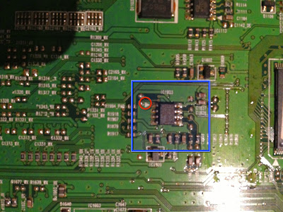
This is how the connector looks on the inside of a TV. If you look really close you can see they are all 3 connected together.

Also notice how fragile the connectors are, I see them broken all the time.


Another Inside picture

This is a closeup of the HDMI processor, the part damaged from power surges


HDMI not working processorThis processor runs on low voltage, typically under 5 volts. So a minor surge from your cable or satellite box will damage this. And in many cases this will cause a TV to not turn on.

Note to those technically inclined: You can't get a meter to the pins on the processor, but if you ohm check across the small surface mount capacitors and read a short, it will (usually) indicate a shorted IC. They are almost always labeled with a C and right next to the ports themselves. I usually read all the capacitors around the processor and ports.


How to protect HDMI

Yes, I'm going to recommend you buy some thing.


In this case spending a little now can save you a LOT later.

The main PCB in the TV in these pictures costs a little over $200 just for the board. You are probably not a technician, so you would also have to pay someone to install and configure the main.
  • 1
    Get a good Surge suppressor, not an outlet multiplier (often sold as surge suppressors. Look for a guarantee against damage to equipment connected to it). Get a surge suppressor with RF cable protection, but first check with your cable or satellite provider to see if this will block their signal

    The ones listed below all fit this criteria
  • 2
    If you haven't done the first thing,,DEFINITELY follow the next two!!
  • 3
    Unplug power to both your TV and STB if a storm is on the way. Don't just turn it off. This also applies to all electronics.
  • 4
    Remove the RF cable going IN to your cable or satellite box.


Surge suppressors that have protection for HDMI


All of these suppressors have a built in RF protectors. Use this to run the RF cable through BEFORE it gets to your cable of satellite box. Usually when HDMI is not working after a surge, it can be traced to an RF line surge that will also damage the cable or satellite box.

This can interfere with the signal level on some satellite systems, check with your provider before connecting the RF line.

What if that didn't help

How to tell if you have a bad cable, port, or no HDMI


ONLY unplug and reconnect HDMI with the TV OFF
First, remove the HDMI cord going to the STB.

Then use another device to test the ports on your TV. Preferably a DVD player that you've tested on another TV with HDMI. Don't connect the STB to the other HDMI ports on your TV!

If only one port is not functioning, check and/or replace the cable with a known good one. I even keep spares in my car. In this article about How to connect a laptop to a TV with HDMI I have a few good HDMI cables listed.

If none of your HDMI ports are working, you probably have a bad HDMI processor (see picture above). You will either need to call a service center or replace the main. Normally a HDMI surge will blow all HDMI ports on your TV.

If this has happened, your STB is bad also. Do not reconnect that box to your TV after it has been repaired, you will end up with HDMI not working again.

Wednesday, December 25, 2013

DELL LCD

DELL LCD TELEVISION REPAIR TIPS

  • Dell w2600: no start-up after warm-up
Model/s: dell w2600 lcd tv
Symptom: no start-up after warm-up
Cure/solutions: replace capacitor (10uf/50v) on small board mounted to power supply next to main-board power connector.

  • Dell w2600: display locks after 10 minutes
Model/s: dell w2600 lcd tv
Symptom: locks after 10 minutes
Cure/solutions: change regulator ic (lm1117 dt-2.5) on main-board

Friday, December 20, 2013

Hitachi LCD Repair

Hitachi LCD Repair Tips

15LD2200 -No-Fuse F1 pictures and C16 or C5 (150N) on the inverter board
-No picture-check fuse F1 and C16 or C5 (15 on) on the inverter board
22LD4200 -Lost picture after diferent time-Dry joints IC100 on board video processor (17MB10).
-Figure disappear after a while-check the connection on the video processor on board IC 100
22LD4200- No pictures sound ok, no pictures after diferent time on 17amp07 CHECK 5v p / s board if less 3.0 or 1.5 replaced C111 (25v1000mkgf)
-There is no sound good picture, no picture after a while check TEG 5v on board 17amp07 p / s if less dar ata 1.5v 3v switch c11 (1000mkgf 25v)
22LD4200 -Lines on the picture Bad conection between PS (PL108) and the video board (PL100).
-The line in the figure because of a bad connection between the PS (PL108) and Board video (PL100)
22LD4200 -line-Green Flashing green horizontal line across the screen intermittently flashing-Remove resistor R149 on the input signal board and replace it with jumper SMD (0 W)
22LD4200 -St-by redlight go green and back to red-transistor (Q104 BC548) and Resistor (100oM).
22LD4500U- No sound- Very low sound on terrestrial and no sound on digital inputs or any AV-memory Replace IC302 Type 24LC16.All customer controls are set to minimum on the new IC. Please reset the language and all the picture controls to normal after replacing the IC.
26LD6200 -Lines on the screen, strange picture-Replaced cable from the main board to the screen.
26LD6200/32LD6200 -No pictures or lost after 10.20 sec-replaced the inverter board (P.Suplly) 17PW11-2 (24Volts)
26LD6200/32LD6200 - The unit does not work, standby LED not lighting-Replace L500 and L501 Ferrite bead with a jumper wire.
26LD6600/32LD6600 - Looks like no-fault Synchro impulse eeprom Just go in service menu (menu, 4,7,2,5)-Factory reset option.
26LD6600/32LD6600 - no sound-Reinstate sound settings as follows:
Enter Service mode.Press menu then 4,7,2,5.
Go to Audio menu.
Select Sound 2. and enter the following values:
FM Prescaler 15
NICAM prescale AVL ON 35
SCART prescale AVL ON 14
SCART VOLUME 122 AVL ON
STANDBY TO GO TO SETTINGS Memorise
Reinstate sound settings as follows.

26LD6600/32LD6600 - Lines on the screen-Cable from the main board to the screen super glue it.
26LD6600/32LD6600 -Lines, pictures no back light present-resoldered IC224 (videoprocesor).
26LD6600/32LD6600 -
28LD5200- No color Colour drops out after the unit has been running for two to three hours.Resolder capacitor C510 and other components in its vicinity.
32LD9700 -No sound bad conection in PFA1 (HDMI board) pin 2 press just take it out and put it back.
32LD9700/42LD9700 -No sound bad soldering on cristal X800 (HDMI board).

Sanyo LCD 42CA8Z

Thanks to DinDik Electronics
The image is blurred or Negative types images are increasingly graying faintly visible 
damage occurs in the IT block-CON (timing control) and I found Faulty ICAS15G


Monday, December 16, 2013

Samsung LA40R81BD

Repairing Samsung LA40R81BD 40in LCD TV Power Supply (clicking Relay Symptom)


Samsung Power Supply (clicking Relay Symptom)

  • Inspect all electrolytic capacitors on the power supply board and replace any that are bulging or leaking.
  • On my board there were 2ea 2200uf capacitors that were bulging.
  • Remove the old capacitors ensuring you don't overheat or damage the copper pads/tracks on the circuit board
  • Take care to ensure you install the new capacitors correctly. They are polarity sensitive and the board and capacitors will be clearly marked which way they should be inserted.
  • You may want to check and replace any adjacent capacitors that are rated 10V as these seem to be the ones likely to fail.
  • In my case I also replaced the 1000uF capacitor
  • If you have a different model TV the layout of the power supply board may be different however the faulty capacitors should be easily identifiable.
  • If replacing the capacitors does not resolve your symptoms you may need to replace the eprom on the main board as it can be corrupted or damaged by the power cycling

Faulty Samsung

Repairing Samsung LA40R81BD 40in LCD TV Replacing faulty EEPROM on main board (Clicking relay symptom)

Replacing faulty EEPROM on main board (Clicking relay symptom part )

  • Turn the main board over to expose the side that was facing the chassis and locate IC1803 (24C256 integrated circuit).
  • Carefully remove the old EEPROM being careful not to damage the copper pads or tracks on the board
  • Use solder-wick to carefully clean the pads where the old EEPROM was mounted
  • Install the new EEPROM ensuring you orient pin 1 of the new device with the correct location on the board.
  • I used an AT24C256C-SSHL-B 8SOIC integrated circuit. There are a number of compatible devices but be sure to get the correct lead spacing to fit the board.
  • Check the solder joints with a magnifying glass to ensure there are no bridges between the EEPROM pins before you reassemble and power up the TV
  • The IC 1803 designation and location on the board is specific to the LA40R81BD model TV.
  • When you power up the TV it may cycle a few times before turning on normally. This is due to the EEPROM being blank and default data being written to it. This is normal. You will need to reset all customized parameters and the date/time in the main menu.

    http://www.googleadservices.com/pagead/aclk?sa=L&ai=Cut0F48nfUsaoMMnakwWAgIG4CLTVrZED1PL4xFe8z5vbwAEQASChpOMNULGo9af______wFgywSgAYiR-fMDyAEBqAMByAPDBKoEnQFP0BUwmjyGd0DDEMbWBQh32VhKMlfgvpShcTJnKGDBJL1LuLIcLSYTCt5sMvc_5nV5DBdwtT4OZLTw27LFT3kbwTe9AYpL7DlLV1NAtjgDEaIH53BAKhcYhIR0cQs94BDi8CwCoia9VMj-cI3LsWCI-UDtqLfgcdZ6DJN3tuVSQQLvumZZDQJqnVCDPDPpM2vvcnSKDVyLYxWENoCuiAYBgAfg7oYM&num=1&cid=5GjpnRv39afdml9opcaiS-TU&sig=AOD64_3U1s3tCktsPNC8ZwCsfhZ_zT1TuQ&client=ca-pub-1990720073119592&adurl=http://www.alldatasheet.com&nm=4&mb=2&bg=!A0TCBE6NFWeJFgIAAAEJUgAAAEUqAOGbv2hWMOSktAl9olRqsb9vLXJuuxaMPgP5AixWRYRi74boQ0itAXlkYhA66MNyrmY4Oi6nS-yEBoPcbJ42lYv6C4-7W1Ln2PdzI8_ozt2yMzqZerQBLFRd6HToowshyLmTWk6jMWGapEfR7QEmU3PROzUzZKfd3Ghz69WcWBMcsuB9tok-XMl10dA1j2Q3omGO9SWsISdtv4scJWdn8-TMmK-7835tBr9C25GqvtoilU5PdgFDezYPYyTy9hYxpUJ3L5NrROUm1jbUIPCTs4IrgoUZKsqmAxmlBv0L30Z2Bzw


NIKAI UHD5501SLEDT Firmware Software Available

NIKAI UHD5501SLEDT Firmware Software Available Follow my page for regular software update NIKAI UHD5501SLEDT Firmware Software Available Mai...